Milling & Routing
Pockets, steps, end features and custom geometry for aluminum parts and profiles.
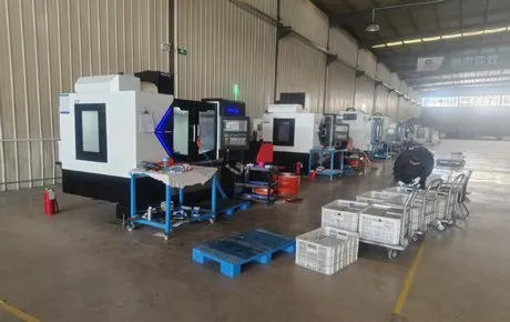
Milling, drilling, tapping, routing, slotting and related secondary operations for aluminum profiles and components produced from approved drawings.
Profile machining
Features placed by drawing
Secondary operations
Multiple features in one route
Fit-focused review
Critical interfaces identified
Ready for finishing
Coordinated downstream work
Machining scope
Operations are planned around part function, datum references, mating components and any finishing that follows machining.
Pockets, steps, end features and custom geometry for aluminum parts and profiles.
Hole patterns and threaded features aligned with hardware and assembly requirements.
Openings for connectors, drainage, access, installation and component interfaces.
Machining coordinated with welding, finishing, assembly, identification and packing.
Production route
The drawing review identifies datums, critical interfaces, later finishing and assembly requirements before machining begins.
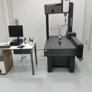
Geometry, interfaces and inspection points are clarified.
Operation order and workholding are reviewed for the part.
Features are produced and relevant requirements checked through the route.
Parts move to finishing, assembly or packing as specified.
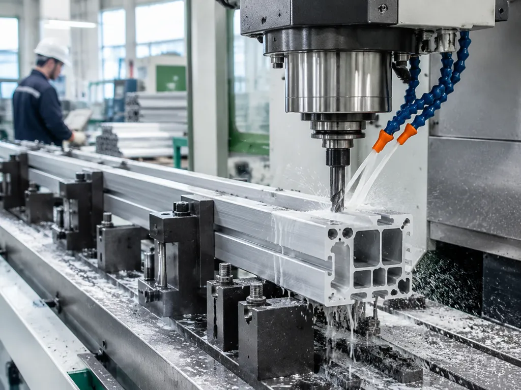
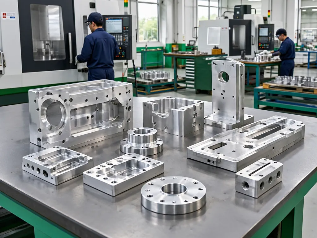
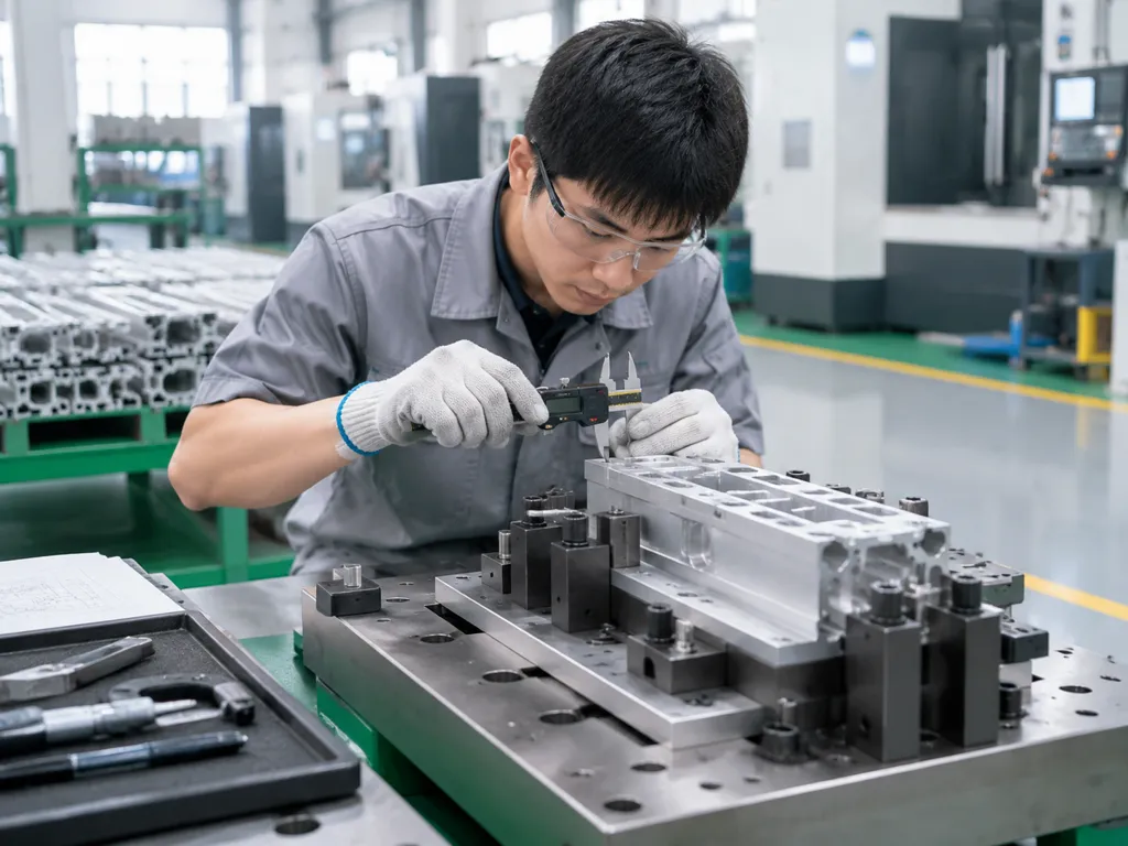
Production and verification
The useful output is not simply a machined feature. It is a controlled component that fits its mating part, accepts the specified hardware and can proceed to finishing or assembly.

Engineering review
For extrusions and long profiles, feature location is only part of the problem. Workholding, datum continuity, finish allowance and the final mating condition also influence the route.
Mark the surfaces and axes that locate the part in its final assembly.
Guides setup, feature relationships and inspection from a common reference.
Show thin walls, open sections, long overhangs and features on multiple faces or ends.
Influences support, setup count, tool approach and movement risk.
Specify thread standard and depth, countersinks, counterbores, inserts and mating fasteners.
Allows functional interfaces to be planned and checked with the actual hardware requirement.
Call out break-edge, deburring and visible-edge requirements where they matter.
Clarifies the delivered state and reduces interference during assembly.
Identify later anodizing or coating, protected threads, contact faces and fit-sensitive areas.
Coordinates finished dimensions and functional interfaces with the surface-treatment route.
Separate critical characteristics from reference and general dimensions; state any reporting need.
Focuses first-piece and in-process checks on fit, function and repeatability.
Parts and operations
Profiles, plate-based parts and matched assembly components present different workholding, access and inspection needs. Only operations confirmed for the actual drawing form part of the quotation.
| Part family | Common drawing features | Planning focus |
|---|---|---|
| Extruded profiles | Cut-to-length ends, holes, slots, taps, pockets and multi-face details | Section support, datum continuity, orientation and visible surfaces |
| Plate and panel components | Contours, openings, steps, counterbores, countersinks and mounting patterns | Flatness, feature relationships, edge condition and later finishing |
| Blocks and custom parts | Multi-level pockets, end features, bores, threads and mating faces | Setup sequence, tool access, critical datums and inspection method |
| Matched assembly sets | Repeated hole patterns, left/right parts and hardware interfaces | Part identification, fit, revision control and kitted delivery |
Typical downstream routes: deburring, cleaning, surface finishing, welding, hardware installation, assembly, labeling and packing.
Review your partCommon machined outputs
The examples below describe output types rather than fixed machine limits. Each part is reviewed from its section, feature access, critical interfaces and final delivery state.
Cut ends, mounting holes, slots and connection features for gates, screens, railings and framed products.
Repeated hole patterns, bracket interfaces, drainage details and end conditions for site assembly.
Contours, mounting patterns, countersinks, counterbores and mating faces prepared for hardware.
Access openings, pockets, ventilation features and fastening points aligned with installed components.
Mirrored or paired components controlled by part number, orientation and assembly relationship.
Identified components, inserts and related hardware grouped for a product or installation stage.
Quality checkpoints
Inspection effort is matched to the drawing. Critical interfaces should be identified separately from general dimensions so production and reporting focus on what matters to fit and function.
Setup, orientation and defined critical features can be checked before repeat production.
Relevant dimensions, tool condition and datum consistency are monitored through the route.
Thread callouts, fits, mating features and hardware compatibility are reviewed as specified.
Burrs, visible surfaces, cleanliness, labels and finish-ready areas are considered before transfer.
From first piece to repeat production
For repeated parts, quality depends on more than final inspection. The drawing revision, setup references, approved first piece and change status should remain connected throughout the order.
Confirm the governing revision, units, material, datums and critical characteristics.
Review orientation, feature access and the stated approval or reporting requirement.
Focus checks on critical interfaces, repeated features, threads and tool-sensitive characteristics.
Keep part number, revision, matched-set identity and approved changes aligned through packing.
Prepare your RFQ
The service is planned for drawing-based profiles and components. Send the section, length and feature drawings for review.
Yes. Surface finishing, welding, assembly and packing can be considered in the overall route.
Identify functional datums, critical mating features, acceptable clamping areas and any thin or visible walls. A 3D model plus a controlled drawing is preferred for complex parts.
Tolerance capability depends on part geometry, material, datum strategy and process. Mark critical requirements on the drawing for review.
Start with your drawing
Share the available model, drawing and application context for a project-specific review.
Global Sales Inquiry
sales@ydaluminum.com
Direct Factory Line / WhatsApp
+86 18265687032 Open WhatsApp